Background
The system is designed and built for the civil engineering department for engineering research purpose.
Objectives
It is built for the research of active vibration control of earthquake/wind excited structures. Also it will be used for the assessment of motion acceptance criteria for human occupancy in the design of flexible structures
Technology
The system consists of a platform with size 3m x 3m which can be controlled to vibrate in a x-y horizontal direction. The kinematic specification is as follow:
Maximum acceleration:
| Maximum acceleration: | 0.3m/s2 |
| Frequency range: | 0.2 Hz to 1 Hz |
| Maximum amplitude: | at 0.2Hz = 186mm at 1Hz = 7.45mm |
| Maximum velocity : | at 0.2Hz = 0.234 m/s at 1Hz = 0.047 m/s |
| Maximum load : | 2000Kg |
CATIA and ANSYS had been used to do the engineering design. The engineering design was proceeded in three different stages which include the Animation; Engineering Analysis and Detail Engineering Design.
Animation
The animation of the whole systems was carried out as that there is a full pictures of how the platform and other major mechanism are going to move.
Click to see the animation of anti-yaw mechanism
Click to see the animation of motion of the shaking platform
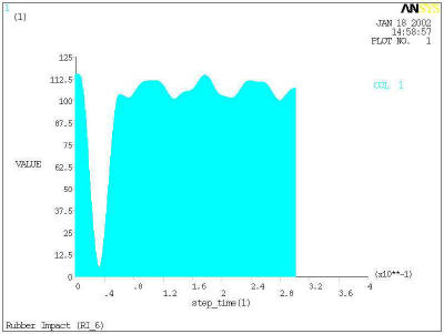
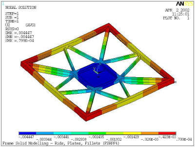
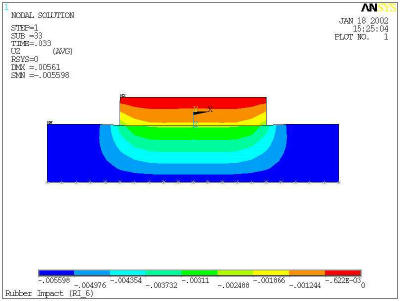
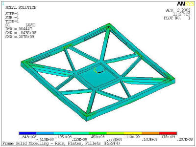
ANSYS was used in the shock absorption analysis, structural analysis and frequency mode analysis. The results is very useful in material selection and component sizing. And it predict the dynamic performance of the system in advance.
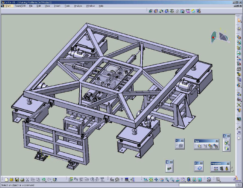
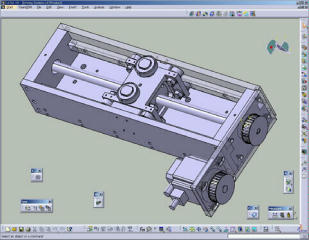
Detail Engineering Design
CATIA provides a powerful engineering design platform to complete the detail design of the complex mechanical system.
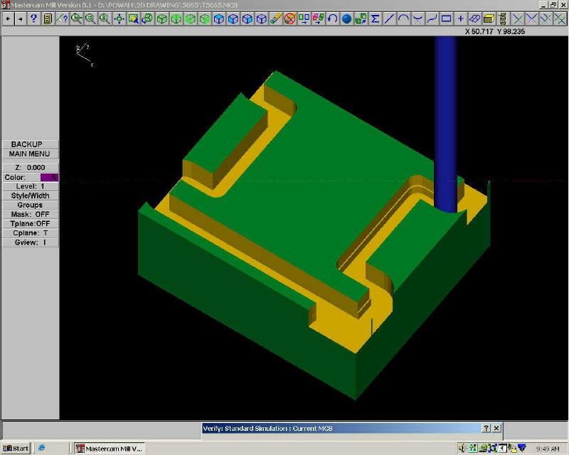
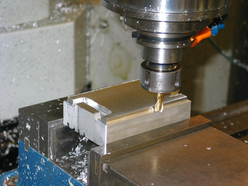
Engineering Fabrication
State of the art CAM software -MasterCam had been used in the fabrication of critical mechanical components
System in Operation
Click to see the machine in operation
Click to see the machine in operation